Tenere 700: Throttle Body Sync Procedure
Tenere 700 Throttle Body Sync Procedure
At 12k km it was time to check my 2021 Tenere 700's throttle body sync, which I suspect is out a little, as the bike is no longer quite as smooth as it once was. This requires some form of vacuum gauge & about 1 hour to remove body panels & tank to gain access to the throttle bodies, sync them & put it all back together....not a difficult job, just a little time consuming.
Bike Specs
- 2021 Tenere 700 Canadian model (Japan Factory)
- 12, 218 km 7,591 miles
- oem original spark plugs
- valve clearance oem factory
- Guglatech Ultra 4 Air Filter + FunnellWebFilters Pre-Filter
- Chevron regular 87 RON unleaded fuel
Required Tools
- #4 & #5 allen, T30 Torx, small diameter punch for push pin connectors, long needle nose pliers, small slotted screwdriver
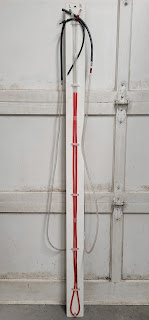
- differential manometer or vacuum gauges - years ago I made an inexpensive & easy to make differential monometer that consists of about 6 meters or 20' of 5/16th" OD/3/16th" ID continuous clear hose filled with red tranny fluid terminating with short runs of 1/8" ID rubber vacuum hoses for better high heat characteristics & leak free fitment on the throttle body vacuum tubes connected to the clear tubing via in-line metal adapters with the left having a T fitting added to the end to connect to the primary TB & air pressure sensor, mounted to a 1.5 meter or 5' tall wood backing plate. The long length of hose, 2 in-line connectors which act as restrictors, 1 T connector & semi-viscous tranny fluid provide ample damping to stabilize the fluid while the bike is running & prevent bounce/flutter. I used an automotive syringe to put the tranny fluid in the hose then hung the assembly up with open hose ends above it for a few hours to allow all air to escape.
- an external fan to cool the radiator during the procedure
- NOTE: the colour of bolts/fasteners on my bike may vary from yours depending on market, bike colour & year

Seat & Body Panel Removal
- review the Yamaha Tenere 700 Service Manual instructions
- remove seat(s)
- remove the front side faring panels (Yamaha calls them "air scoops") using T30 torx for the 3/side silver bolts + 3/side raised push pin torx bolts (requires 1/4 turn counter-clockwise) flanking the radiator to release the front side panels - slide panel back, then up, then out to release the tab from the rear slot & unseat the locating pins
- remove the 2 side panels under the tank using #4 allen - it is not necessary to remove the lower front bolt of front louvered panel (Yamaha calls them "air ducts") under the tank - the rear fuel tank side covers includes 1 recessed #5 allen & 1 black #4 allen bolt on the back of the tank per side (the lower back ones, the 2 upper back bolts securing the painted tank plastic do NOT need to be removed)
- Tech tip: it is NOT necessary to remove the 2 push pin connectors in front of the fuel cap or the painted tank plastic cover
Tank Removal
- review the Yamaha Tenere 700 Service Manual instructions
- Tech tip: it is easier with very little fuel in the tank - run it well into reserve prior to syncing, or siphon fuel out of tank, if desired & NOTE the position of all rubber & foam pads on all inner surfaces as they have a tendency to dislodge & fall off...perhaps a good time to reattach with glue or 3m adhesive tape.
- remove the 2 push pin connectors (1/side) fastening the plastic front mount to the tank
- remove the 4 black #5 allen bolts from the rear tank mount
- carefully pull the tank rearward while wiggling it slightly side to side to release it from the front rubber mounts & raise the front up supporting the tank mount on a shop towel & securely support it to provide access to the TB
- Tech tip: do NOT stress the fuel pump wiring harness & fuel/vent lines & leave them connected to facilitate warming the bike up prior to performing the TB sync.
Throttle Body Sync
- review the Yamaha Tenere 700 Service Manual instructions & ensure throttle cable is adjusted correctly, throttle does not stick, air filter is clean & bike idles normally & at correct rpm in addition to the checklist in the Service Manual below.
- warm up bike fully, keeping temperature below the fan turn on temp throughout the procedure...an external fan directed at the radiator helps stabilize temps, along with minimizing the time that the engine has to idle
- Tech tip: for best results avoid performing TB sync during extreme humidity & temperatures
- using a long needle nose pliers carefully remove the rubber vacuum line cap from the right TB & attach the right gauge hose
- remove the left TB vacuum hose from the air pressure sensor located above it by the frame & attach the left gauge T connector hoses to the sensor & the TB vacuum hose
- start bike & ensure no vacuum leaks or kinked hoses
- the left TB is the primary set by the factory - the service manual stipulates adjusting the right TB air bypass screw to sync - adjust to the desired setting using small increments - after each adjustment rev the engine 2 or 3 times, each time less than 1 sec & allow the idle to settle
- Tech tip: if idle is erratic or synchronization cannot be acquired, check for an air pocket in the manometer fluid (it can take several hours for them to dissipate via gravity) and/or vacuum leak and/or kinked hose or other problem that may require further investigation or dealer service
- Note: the differences in height of the fluid in the left & right hose on a differential manometer do not necessarily equate to large pressure differences between throttle bodies because it is using the same fluid reservoir with opposing pressures, so a 1' to 2' difference may appear alarming but not actually a large pressure difference & hence not a large disparity in throttle body sync...in this regard the manometer displays relatively small pressure differences between throttle bodies & why only very small adjustments of the air bypass screw are needed to move the left & right lines closer together & obtain sync...the goal is to get them as close & stable as possible
- shut off bike, remove the gauge hoses & re-install the left TB hose to the air pressure sensor & right TB vacuum line cap & restart to ensure proper operation
Reinstall Tank, Body Panels & Seat(s)
- reverse of removal procedure starting with tank, then the 2/side lower panels under the tank, then the large front side panels & the seat(s) last
- Tech tip: use blue locktite on all bolts
- Tech tip: reset all push pin connectors by pushing the inner extended part back into its housing prior to re-installing on bike - once properly in place push the extended part in until in snaps/pops in place to lock them - the raised Torx head ones can be a little finicky, so ensure that they are fastened properly before riding...I lost one that had not fully snapped into place
Install Tank
- once tank is securely pushed forward & seated on the rubber mounts install the 4 rear tank mount #5 allen bolts - NOTE that the tank sits on the large rubber frame bumper & that the rear tank mount pivots on the upper 2 bolts & the lower section may not sit flush with the frame mounting point until those 4 bolts are tightened
- do not forget about the 2 push pin connectors at the front of the tank
Install 2 Under Tanks Side Covers
- see pic below for overlap fitment of the front side air duct cover & rear side fuel tank cover, NOTE that this bolt is a long black #4 allen
Install Large Front Side Panels
- position the body panel rear locating tab above the upper rear slot, insert down into the slot, then slide forward & while aligning the panel locating pins with their respective holes position the panel correctly & install the 3 #30 Torx bolts & 3 Torx head push pin connectors flanking the radiator
Install Seat(s)
- test ride time 😀
Here is a video by CVB ADV that provides a good overview of a Tenere 700 TB sync


Comments
Post a Comment